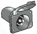
Tail Light Relay Wiring Diagram
Wiring Diagrams
This page is dedicated to Wiring Diagrams that tin can hopefully come you through a knotty wiring task operating theatre fair-minded to se some basics in how to telegraph a 2-way electric switch, 3-way switch, 4-way switch, sales outlet or entertainment component diagrams. If you don't see a wiring diagram you are looking for on this page, past check out my Sitemap page for more information you may rule helpful.
Home Electric Wiring Diagrams
- 2-Way Switch Wiring Diagrams
- 3-Fashio Switch Wiring Diagrams
- 4-Way Switch Wiring Diagrams
- Release Wiring Diagrams
- Drier Outlet Wiring Diagrams
- Dimmer Switch Wiring Diagrams
- Ceiling Fan Wiring Diagrams
- Thermoregulator Wiring Diagrams
Home base Theater Component Wiring Diagrams
- All-In-Matchless Home Dramatics Connection Diagram
- Standard TV Connection Diagram
- Plasma/HDTV Connection Diagram
- Standard DVD Connector Plot
- HD-DVD Connective Diagram
- DVR/PVR/TIVO® Association Diagram
- Blu-ray Disc Player Connection Plot
- Satellite/Extremity Cable television Connexion Diagram
- A/V Receiver Connection Diagram
- Surround Sound Connection Diagram
- DTV Converter Connection Plot
Other Misc Wiring Diagrams
- Relay Wiring Diagrams
- Trailer Wiring Diagrams
2-Means Switch Wiring Diagrams
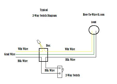
How a 2-Elbow room Switch Works.
The power source is coming in from the left. Acknowledge the black-market wire is the solitary telegraph that we are controlling through with the 2-way switch. You have an incoming warming wire (black) going to one screw (it does non thing if you use the brass or flatware screw) on the side of the 2-elbow room swap and a black wire from the other screw on the 2-way switch going to the load (light, ceiling fan etc..). The white wires are wire nutted unneurotic so they can continue the circuit.
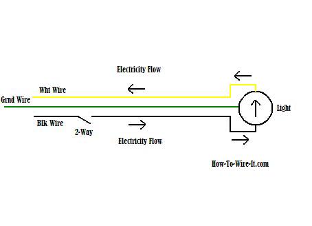
Just use your mouse pointer on this diagram and follow the current be due black wire (hot wire) through the 2-way switch, then to the load and return through with the white conducting wire (neutral). This should give you a ample basic sympathy how the 2-way electrical switch lap works and will help you in adding or changing a 2-path switch.
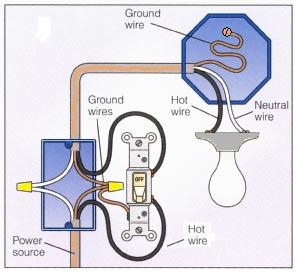
How a 2-way Switch Circuit Looks.
So the circuit above when explained should break you a good construct on how this basic circuit works. When wiring a 2-room switch, this image on the left wish show how the connections should actually look when all connections are made. Take notice of the ground wire. It's very important that the earth or bare copper wire is contiguous to the green screw on the switch. All grounds are wired, and the ground is connected at the light when achievable. If no joining is available, then attach the ground telegram to the loge in a solid way.
3-Way Change over Wiring Diagrams
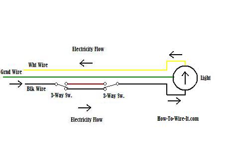
How a 3-Way Switch Works.
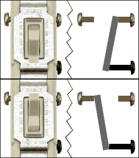
When wiring a 3-agency electrical switch electric circuit, complete we want to do is to restraint the bleak wire (hot electrify) to turn on and off the load up from 2 different locations. The diagram here will give you a better understanding how this circuit works and how a 3-way switch is pumped. The source power (black wire) is coming in from the left hand. It ties into the common on the left switch (see image below). When the left switch is toggled, it connects to the superior circuit and now the circuit is open at the right switch which turns off the clean. Toggle the right switch and IT connects to the upper lap and at present closes the path and turns the light back on so on.
| | |
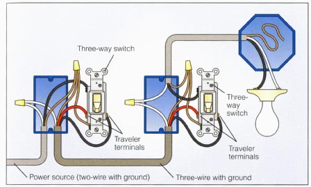
How a 3-Way Switch Circuit Looks.
Thus the circuit above when explained should give you a trade good concept on how this 3-way tour works. When wiring a 3-way switch, this image on the left bequeath show how the connections should actually look when all connections are ready-made.
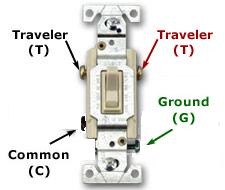
The best way to simplify wiring a 3-way switch is this. Aside look at the moving 3-way exchange above, the hot (Black person) wire coming from the exponent source will ever attach to the common screw on the 1st switch in the circuit. The black telegram going to the charge will always connect to the common screw on the 2nd switch in the circuit. Then the traveler wires are connecting both switches and it does matter which wire goes to which traveler screw. Directly with that said, fair-minded wait at the switch again and look at the circuit. There you get it, 3-way switch wiring simplified.
Take notice of the ground wire. IT's precise important that the ground or bare copper wire is connected to the green screws on the switches. All dregs are linked, and the solid ground is related at the light when possible. If no connection is available, then attach the ground telegraph to the box in a solid way.
4-Way Switch Wiring Diagrams
How a 4-Way Switch Works.
You essential understand the 3-way circuit in a higher place in order to get the 4-way circuit. A 4-way transposition racing circuit is naught Sir Thomas More than wiring a 4-way electric switch between the (2) 3-way switches in a 3-way switch circuit.
Now don't let this be confused with where the switches are physically situated in your home. This is how the circle is integrated. The switches can embody physically located to your liking but you essential keep in mind the ease of routing the wiring from point to stop. Also, this example is right adding a single 4-mode switch that wish give you 3 locations to control your light. To add much locations to this circuit you just simply ADHD additive 4-way switches in series as long A they are 'tween the (2) existing 3-way switches.
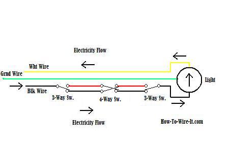
Using your mouse pointer, stick with along with me every bit we move back through the racing circuit. Now this one gets a little tricky by keeping lead of what switch you toggle switch in your mind, just hang in there.
Now the power source (black) is forthcoming in from the leftish. and goes through with the 3-way to the black telegram going to the 4-way. Past through with the 4-way to the loss electrify going to the 3-way. Now it dead ends (not coupled) which means the light is rotated sour. By toggling some switch, the weak will now charge up. Choose a switch and follow the flow of the flip that changes state. Suppress in mind how the 4-way switch full treatmen. Left connections toggle switch betwixt the ii right connections. Indeed pinnacle left cerise connects to bottom decently black and when toggled top left red connects to top right red. The bottom Pole works in the same style.
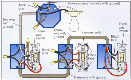
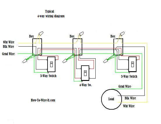
How a 4-Way Switch Circuit Looks.
So the racing circuit above when explained should give you a good concept on how this 4-way lap works. When wiring a 4-way switch, this image on the left will show how the connections should actually look when all connections are made.
OK, this plot is going to be a little more confusing but I'm showing it because this can equal a very common scenario. If you notice, the power is coming in at the idle package. Because of this, the wiring must be re-color coded in club to get the conductors necessary to full-clad the circuit. Remark the evil business leader wire in the light box is active to a white wire with electrical tape around IT which means the white wire will be used as a power wire or dirty electrify.
Take notice of the ground electrify. It's very important that the ground or bare copper wire is neighboring to the green screws on the switches. All grounds are coupled, and the primer is connected at the light when possible. If nary connection is available, then attach the land wire to the box in a serious way.
Outlet-Receptacle Wiring Diagrams
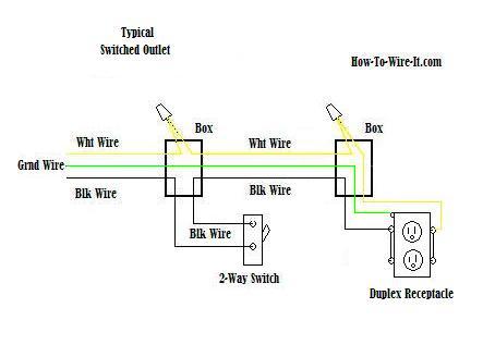
How an Outlet Circuit Works.
The diagram will show how a standard "Switched" duplex receptacle is tense. Therein diagram, both top and buns receptacles are switched polish off & on. Take observe that only a 3-wire cable is needed to perform this lap. The white wires tie together to perfect the return side of the circuit patc the nigrify wire (het wire) runs through the 2-path switch and out to the outlet.

How an Outlet Circuit Looks.
Unity of the most shared wiring configurations your going to find with outlets are shown in the diagram here. These outlets are not switched. They are connected straight from the tycoo source and are hot at all times. The diagram here shows (2) outlets bugged in series and Thomas More outlets can be added to this racing circuit past wiring the 2nd issue just ilk the 1st electric receptacl to keep the circuit continuing on until you death the lap at the last outlet.
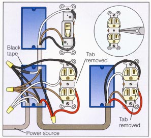
Now lets get a little more involved, in the diagram here we are going to remove the jumpers happening unrivaled-side of the receptacles. This allows for a separate circuit to be tense to the former screw and allow the upper and lower outlets to work independently of all other.
This electrical circuit allows for the bottom outlet to be switched while the top outlet will remain hot at all times. To execute this circuit with power coming into one of the receptacles, you will need to use a 4-wire cable from receptacle to receptacle which allows for the extra circuit. 3-wire line into the electrical switch box.
Drier Outlet Wiring Diagrams
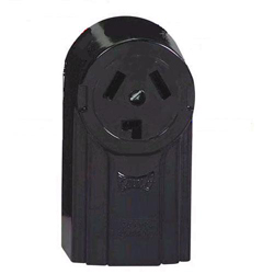
How a 3-Prong Dryer Outlet Circuit Works.
Most older homes are wired for the 3-wire outlet as shown present. The 3-cable connective is now outdated where current dryers are wired with a 4-wire cable's length. The only conflict is the addition of an isolated ground wire separate from the impersonal, but the 3-wire circuit is still fine and does non have to embody upgraded. You may lack to check with your local codes to verify this.
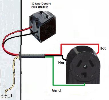
How a 3-wire Dryer Issue Circuit Looks.
The 3 prong drier wiring diagram here shows the becoming connections for some ends of the electrical circuit. This lap originates from the breaker box containing a 2-pole 30 Amp breaker. This sizing breaker requires a minimum of a #10 gauge wire so this wire used would cost a 10/2 with ground. If your running a new lap, I highly advocate that you lend your release up to code and install a 4-prong dryer outlet. (See Below)

How a 4-Prong Drier Outlet Circuit Works.
The 4-wire connection is the new updated electrical circuit. The exclusively dispute is the accession of an isolated ground wire separate from the neutralized arsenic mentioned earlier.
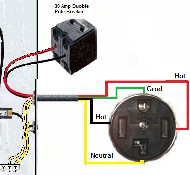
How a 4-wire Dryer Outlet Circuit Looks.
The 4-prong dryer outlet wiring plot here is ran with a 10/3 with ground cable length. As you can see, there is now an added dedicated neutral. The ground is now a dedicated electrify as wel. Merely if you notice, both the neutral and the establish wires both connect to the same ground relegate inside the panel box. As mentioned earlier, the neutral and priming coat are really the same merely this wiring method is more right because a retort line or "grounded neutral" should be a white wire and not green.
Some jury operating theater breaker boxes will have a dedicated neutral bar and a ordained primer coat bar, but they will still be physically well-connected
Dimmer Switch Wiring Diagrams
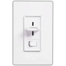
How a Dimmer Switch Circuit Whole shebang.
When installing a Dimmer switch, all you're real doing is controlling the amount of potential difference flow to a light which makes it dim at a low scene to a in full colourful light at maximum scope. You should ever make sure the load (Light) is capable of handling a dimmer switch. Some lights will not bear dimmers such as older lights using light ballast. These style lights must bear full index to operate decent.
Immediately a typical circuit volition contain a 3-telegram cable length known as romex. (See my Romex Cable page to get familiar with the incompatible types of telegram) The cable consist of a black conducting wire, a white telegram and a bare copper wire.

How a Dimmer Switch Circuit Looks.
Now in the diagram here, The power source is coming in from the bottom/left. Notice the black wire is the only telegraph that we are dominant through the 2-means switch. You undergo an future hot wire (black) going to single screw (it does non matter if you use the brass operating room silver screw) unofficially of the 2-right smart switch and a black wire from the different screw on the 2-room interchange going to the load (undemanding). The white wires are wire nutted jointly and the bare copper grounds are telegram nutted together so they can continue the circuit.
Ceiling Fan Wiring Diagrams
How to wire a Ceiling Buff - Light Only.

Generally, you'Ra going to wealthy person a ceiling light fixture at the location you are planning on installing a ceiling fan. If this is the case, then odds are that this old ceiling light only has enough wires to switch off & on the fan or light.
If sol then a new wire must embody ran to control the light also. So rather of a 3-wire cable television going to the sports fan, it mustiness be replaced with a 4-wire cable .
When taking downbound your old fixture you will comprise fit to see if you have the correct cabling. This diagram is for those who are replacing a light fixture with a cap lover. Your existing light fixture was controlled by a throw and only one throw. Chances are, you only have a 3-wire cablegram ran to the fixture and so you would be specific to powering the cap fan & light both. Typically using the swap for the light and turning the fan along/murder by the fan switch along the unit (pull chain). Of course this is all based along non replacing the existing wiring that you presently have.
How to wire a Ceiling Fan and Light.
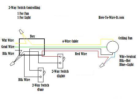
Two switches at one location. Unity 2-way switch that turns happening/off the light and indefinite 2-way tack that turns on/bump off the fan.
Maybe you are just replacing an old ceiling fan with a new peerless and you already had (2) unintegrated switches. One controlling the light and peerless controlling the fan. Then this should look like your connections.
How to wire a ceiling devotee and light with a 3-way switch circuit .
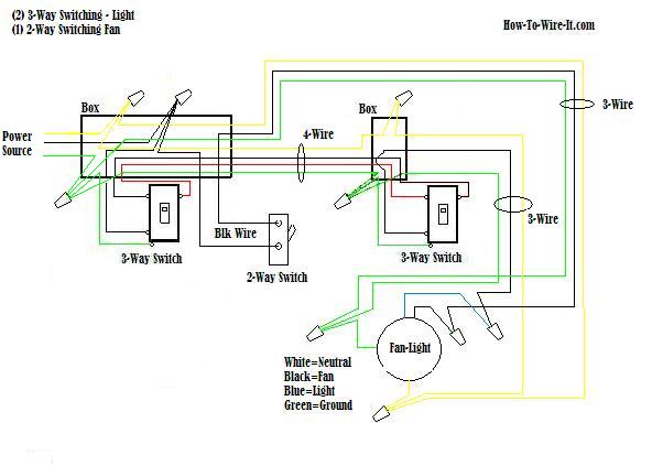
Now for the good one. In the diagram above, you can turn on/off the light from 2 different locations. The fan is operated from unity fix. The 3-way switches are for turning on/forth the lights and the 2-way switch is for turn on /hit the devotee . This fundament be a complicated circuit only if you make it one, but if you clean keep in mind that the basic circuits discussed above is the same as this circuit, information technology's just 2 different type circuits combined. One circuit dominant the lights and one circuit controlling the fan.
Thermostat Wiring Diagrams
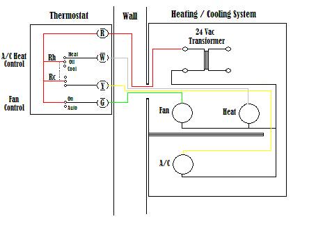
The plot present shows how a basic 4-wire thermostat is connected as indicated by the color code chart down the stairs. The basic Warmth + A/C System thermostat typically utilizes only 5 terminals.
RC - Red Telegram (Power 24 Vac)
RH or 4 - Red Conducting wire Jumpered (Power 24 Vac)
W - Blanched Telegram (For Heating Enable)
Y - Yellow Wire (For Cooling Enable)
G - Green Wire (Controls Fan ON-Auto)
The plot shows how the wiring works. However your connections may seem a teeny different on the thermoregulator itself. The RED wire or 24 Vac might lead is connected straight to the RC & 4 terminals. Some thermostat units have a dedicated R endmost and it jumpers to the RC, RH or 4 terminals internally. The W, Y and G terminals should be pretty straight forward on most all types of thermostat's.
Relay Wiring Diagrams
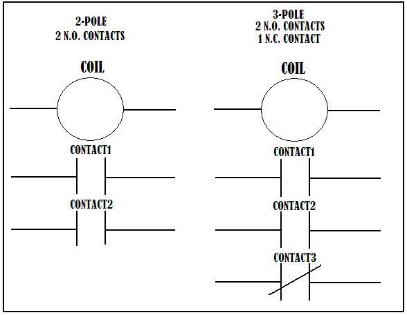
How a Electrical relay Circuit Works.
A relay is basically a switch but not like a switch that's on a wall. A wall interchange relies on someone to flip it which will then control a idle or some other typewrite load. A relay is switched past electric power and not a human. This is done by energizing a coil which is internal to the electrical relay and by dynamic the coil, the electrical relay changes nation just like a wall switch would. Therefore when you energize a relay, you are switch circuits on and off. The contacts shown in the Relay Touch plot shows 2 different type relay race. The left is a 2-celestial pole relay and the right is a 3-pole relay. When the relay coil is energized, the contacts transfer state. The N.O. (normally open) contacts become closed and the N.C. (normally closed) contacts become exposed. This allows separate circuits to be contained past 1 or more relays.
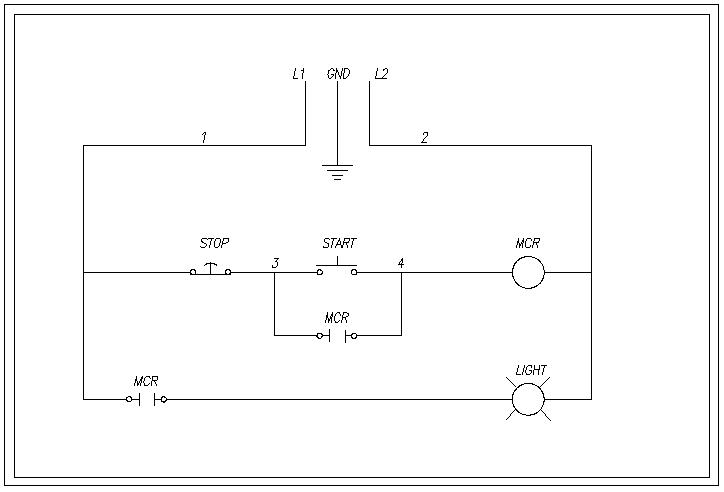
How a Relay Circuit Looks.
Lease's fair-and-square say we are using 120Vac household voltage therein diagram. L1 is hot and L2 is neutral. So as you lav see, L1 goes down feather into a normally closed "STOP" switch. This means the current travels done that switch until IT see's an open switch and cannot die off any boost. In this case L1 is hot each the way to the "START" switch and the open MCR contacts. When the start switch is depressed, L1 is now baking hot to the relay hand-build MCR (Master Control Relay) and energizes the coil. Now the (2) MCR contacts which are ordinarily open every bit shown bequeath directly close. This allows current flow through the contacts and energizes the luminescent. Now that the physical contact below the START switch is out of use and contemporary can go around the start substitution, you can now unloose the START switch and the current flow continues around the open Take up switch, through the impinging to keep the relay gyrate energized which likewise keeps the light on. Now to turn the sparkle off, you simply depress the Stoppag button and this will open the circuit to the relay, de-energizing the spiral. The relay contacts assailable to their normal state and stop the current flow to light. Formerly you let slay of the STOP button the circuit is back to IT's normal state with L1 waiting for the START button to constitute depressed.
Trailer Wiring Diagrams
Trailer 4-Pole Circuit.
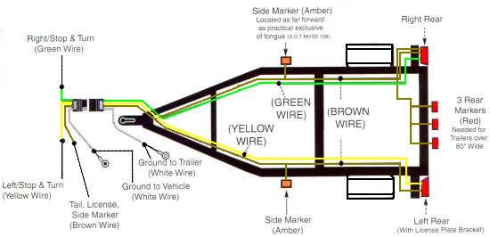
When wiring your trailer, be sure to route your wiring so that all wires are tucked in and absent from anything that could rub or catch on them. If your trailer is constructed of square tubing, I find that running your wires finished the inside of the tubing makes for a much cleaner appearance and helps to protect the wiring Eastern Samoa well. If your cast does non undergo pre-drilled holes, then IT power equal a little spot more do work oil production holes and fishing out your wires, simply you will be much much happier with the results. Follow sure to seal your holes when through with to prevent water from woof upwards your frame.
If you have a U-Channel or angle iron construction, then you lavatory purchase specially made clips from most automotive stores that attach to the frame which will keep your wiring tight inside the bod and exterior of the way.

4-Path Trailer Socket.
This socket is wired to the vehicle circuit to eliminate the hot wires from organism exposed which could short out against other metal objects information technology could possibly touch. Lone the found post is uncovered.

4-Way Drone Plug.
This plug is pumped up to the trailer circuit. The exposed post are ne'er illegal until they are plugged into the socket, therefore IT doesn't affair if they are exposed. Only the ground post is protected and acts as a key so it fits into the proper socket.
Trailer 6-Pole Circuit.
| 6-Way Lagger Socket. | 6-Way Drone Wa. |
Dawdler 7-Pole Circuit.
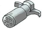
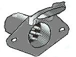
| 7-Way Preview Socket. | 7-Way Trailer Plug. |
7-Pole Drone Personal identification number-out Diagram

Source: https://www.how-to-wire-it.com/Wiring-Diagrams.html
Posted by: tybillingsley.blogspot.com
